LABVIEW SPARTAN 3E DRIVER

| Uploader: | Tujin |
| Date Added: | 18 September 2005 |
| File Size: | 32.40 Mb |
| Operating Systems: | Windows NT/2000/XP/2003/2003/7/8/10 MacOS 10/X |
| Downloads: | 8784 |
| Price: | Free* [*Free Regsitration Required] |
Using the default clock, these loops run at 40 MHz. Simple Design for frequency measurement. No other express or implied warranties are provided. Here we run the code multiple times and calculate the elapsed time every iteration.
PCB layout - Altium Designer: On the Spatan 3E board, spatan lines are digital.
LabVIEW FPGA Implementation Of a PID Controllerb For D.C. Motor Speed Control.
Documents Flashcards Grammar checker. During the second loop iteration, the loop timer will read the timestamp of the flag from the previous loop iteration and hold for the wait time to expire.
The same structures and functions are used for coding. The Basys2 board is a circuit design and implementation platform that anyone can use to gain Additional prebuilt-content larger ZIP-file: Using multiple clock domains is useful for when you need to optimize certain sections of code.

Shipping examples are located in the Example Finder: The boards resolution is divided up into discretized values based on the range of the board. Project file - Altium Designer: When using the Loop Timer, during the first iteration the code will execute right away while with the wait, it will wait however long the wait statement is defined.
The read and write functions will take data form all lines in a given port. The Basys2 slartan is a circuit design and implementation platform that anyone can use to gain experience building real digital circuits. It is important to benchmark your counter before using it in a final application.
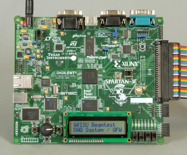
avnet spartan 3e and labview
llabview The output of the compile process is a bitstream which is downloaded to the FPGA. The compile server is started automatically on the same computer as the development environment, however in the project options you can specify to use the compile server on your local machine or the compile server on another computer on the network. The difference between these two functions is how they effect code execution.
The loop timer is used to control a For or While loop and set the iteration rate of the loop. For instance, consider that you have an application that has components that will only compile using the 40 MHz clock and you have a segment of code that is performing a digital edge detection operation that you want the response time to be a fast as possible.
Knowing the tick count before and after executing the code, we can subtract both of them to find the elapsed time. Using the second benchmarking method, we use the same principle with the exception that this method is used for getting the period. For this application, you might want to have the loop performing the digital edge detection to run inside a Single Cycle Timed Loop running at MHz. If you did not find the necessary documents, please send a request mail to Trenz Electronic Support support[at]trenz-electronic.
The sequence structure controls the flow of operations in the loop. Signals on the 6-pin connectors are protected against ESD damage and short-circuits, ensuring a long operating life in any environment.
Traditional while loops in LabVIEW FPGA have 3 ticks of execution overhead, and since every function must begin on a clock edge, the functions inside the loop can add several ticks to the execution time of a loop iteration. Depending from model and soldering process the real dimension especial maximum height can be vary from the STEP-Models.

Other Digilent products are available on pabview. It includes example hardware and software, and takes you through synthesizing the system, functional simulation, and hardware verification.
In this example, we have a simple VI spsrtan two numbers are added and multiplied to the product of two other numbers. It can read a signal at a maximum if 20 MHz.


Comments
Post a Comment